Archive for the ‘repair’ Category

Fixing my MTB dropper post cable

June 8, 2019

Not dead yet. Been busy with work and other things.

Another in my series of infrequent updates, a little thing I’ve made better.

To the subject: I fitted a cable-release dropper post to one of my mountain bikes. I noticed the action of the cable release was not particularly reliable, and no amount of fiddling and tweaking seemed to fix it.

I even bought a replacement handlebar lever. PNW do make fine dropper post levers, although they are slightly spendy.

I still had a problem. It might be related to the cable location, or nature of the cable run. I was happy with where the cable was, and did not want to move the cable.

The seat post’s internal release mechanism didn’t seem to create much tension in the cable. On the one hand this is desirable, except when there’s an excess of friction in the cable run.

The solution which works for me is to buy (or otherwise acquire) a small spring. I found a spring with these dimensions fits and works:
Overall diameter 5mm
Wire diameter 0.5mm
Length 20mm

Just insert the spring under the release lever like this (the nub on the cable end just fits through the spring):

20190331_154809a.jpg

Job done, go out and ride!

LED Moving Message Signs

September 17, 2018

Preface:
Apparently they are still “a thing”. The reasons I’m writing this are:
1. I still find I’m being asked about them.
2. Since TalkTalk ceased their user webpages service, this information has nowhere to live … until now.
A long time ago I used to work in a local cinema as a film projectionist. When cinemas had film. I don’t know if it was peculiar to the site where I worked, but I was expected to be the “fix everything” person. So this included a set of moving message LED signs imported from somewhere. Over some years I identified some problems which happened time and time again. I had a summary of the information I knew, with information I had gathered from other sources. I reproduce that information here, as it still seems to be useful to some people.
I note that the manufacturer is still trading, but the products listed here are considered obsolete.
What follows is more-or-less a copy-and-paste, with some minor edits to remove dead links.


I was asked to repair a “faulty” electronic sign. When connected to the power, it would boot correctly with version information e.t.c. Immediately it would then freeze, with gibberish in the display.

I reasoned (guessed really) the sign’s internal, battery-backed RAM, was corrupt and causing the sign’s OS to crash. The external keypad was being ignored.

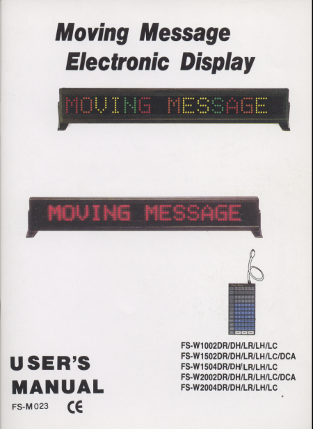
This could apply to so many models of electronic signs produced by various companies, the sign I repaired is model FS-W2002DCA. Due to the economies of scale, a single control PCB is manufactured and populated with different RAM chips, and different EEPROMs to make the different signs in the range:

FS-W1002DR
FS-W1002DH
FS-W1002LR
FS-W1002LH
FS-W1002LC
FS-W1502DR
FS-W1502DH
FS-W1502LR
FS-W1502LH
FS-W1502LC
FS-W1502DCA
FS-W1504DR
FS-W1504DH
FS-W1504LR
FS-W1504LH
FS-W1504LC
FS-W2002DR
FS-W2002DH
FS-W2002LR
FS-W2002LH
FS-W2002LC
FS-W2002DCA
FS-W2004DR
FS-W2004DH
FS-W2004LR
FS-W2004LH
FS-W2004LC

Of course, the above list is for the benefit of anyone using a search engine.

The repair works by removing the RAM from the battery back-up. Really what you are doing is giving the sign a factory reset.

Remove one of the end caps of the case, remove rear panels until you can get to the central control circuit board. If there are lots of socketed ICs, you’re in luck. Remove them all, making sure you take note of their position and orientation. Take your time with this part of the task.

Replace all the ICs in the correct sockets, and re-assemble the sign.

The sign should now work correctly. If it doesn’t, it was beyond repair before you started.
Other information:

Since I created this page, I’ve been contacted by others who have encountered these signs. They have provided me with some other information about these signs. To quote part of one email from one of them:

I managed to get hold of a keyboard for the display (on loan), but what I have discovered is that it does not communicate via RS232, much to my frustration…. because the plug on the back of the display is not standard 232, other pins are sent to the keyboard (TTL level). I can now set the clock with the keyboard, but I still cannot set it via the PC. The keyboard sends something other than RS232 signals, it looks like 8 bits similar to 9600 baud, but is not standard i.e. pressing “1” followed by “2”, does not produce a 1 bit change. There is also a bit allocated to wether the key is pressed or released.

I have also been given this URL: http://www.fspring.com.tw/fspring/pages/downloads.htm which (see comments for an alternative link) seems to be software to control the signs from a PC via a serial port. I went back to the manual and scanned a couple of pages:

Front cover

sign_front_cover
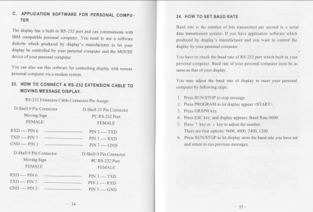
How to make an RS232 adapter (actually useful!)

sign_manual_1
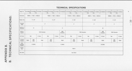
Features of the various models of sign

sign_truth_table

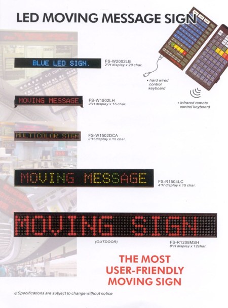
This is an image I didn’t scan, but it seems to be of a publicity flyer for some of the signs in their range, including some signs not listed above.

LedMove

In case that page referenced above moves, you can download the PC control software and manual from here (edit: see below). The manual is in Word format, and OpenOffice 2.0 opens it without fuss.

SSign_MANUAL

Alternative link

I’ve not tested the control software, and I probably will not be able to do so in the near future.
Repairing the keypad and its cable.

After a while the keypad will stop working, this is likely to be either the 9 way D type connector being worn, or the cable being worn. It’s not a standard RS232 cable for two reasons: (a) there are power connections on pin 8 and 9 and (b) the Rx and Tx lines are not on pins 2 and 3.

It is a simple task to replace the plug (and cable), and I hope you find this drawing helpful.

PinOutElectronicSign

Repairing the connector on the back of the electronic sign.

You might observe, after a lot of useage, that the 9 way D-type plug becomes loose on the PCB within. This is because there’s no strain relief on the plug body. Equip yourself with a straight-PCB-mount 9W D plug (RS components part number 472-758). You’ll need to disassemble the entire case, including all those small black screws from the various back panels.

The main control board can be readily unplugged from the display panels, and it’s easier to work on that way.


Replacing the sub-bass driver on a Mission FS2-S.

July 12, 2015

My long-serving Mission FS2-S sub-bass driver succumbed to the passage of time recently, and the rubber diaphragm started to disintegrate. The driver needed replacing. A forum post revealed that Mission would sell you a replacement driver, in October 2014. When I spoke to Mission’s technical department, they don’t stock that driver and that was the end of it as far as they were concerned.
The satellite speakers only work with that cross-over and filter, and I was not ready to replace the entire system. An alternative strategy is to remove the failed speaker, and use a separate (amplified) sub-bass driver. That’s ok, but it’s a second big black box in the corner.
After a bit of searching for 8 ohm 6.5 inch speakers, I found that the Visaton W170 appeared to be a drop-in replacement. The power rating is not quite as high as the original part (40W versus 55W for the original). But the fixing centres are in the same place, the speaker physically fits in the cabinet, and it even has the same spade terminals. For a mere £20, it’s a bargain repair. Very easy to do. The only “trick” is that the rubber grommets which hold the dust cover on are hiding 6 screws which need to be removed.
As Mission were asking for £40, the price looks brilliant.
I listened to the first twenty minutes of my Blu-ray edition of Blade Runner on it, and it sounded great to my non-calibrated ears.

P1010363

Little surprises in electronics.

October 4, 2014

On a cheap Yuan Hung Lo MR16 LED lamp, it was a pleasant surprise to find silkscreen print on the tiny PCB showing the orientation of the surface mount rectifier diodes.

SMT diode replacement on a MR16 LED lamp.

SMT diode replacement on a MR16 LED lamp.

I had taken a photo of the board before starting work, and I will be cleaning off the flux before putting the lamp back in to service. At this stage I had only replaced two of the four diodes.

Ford Focus Mk2 key fob repair.

January 29, 2014

Are the buttons not working properly on your key fob? Order three KSR211GLFS Tactile Switches, and break out the soldering iron. I was able to buy them for a sensible price on ebay.

I’m writing this up because I saw the part number on someone else’s blog, and I can’t remember the URL or name of it. To that mystery person, thank you for posting the part number.

Embracing the repair-not-replace culture.

December 30, 2013

A friend asked me to look at two pairs of GHD brand hair-straighteners. She wanted to know if I could produce one set which worked, from the parts. As I was fault-finding I quickly became aware that the hair straighteners were designed to be repaired. There were no glued or ultra-sonically welded parts, just simple screw fasteners. This is not the modus operandi of a company which produces poor quality products. The manufacturer seems to want their customers to be happy with their products, while keeping imitation products off the market. By making the genuine article simple to repair, people are less likely to buy a cheaper counterfeit.
That’s my theory anyway, your mileage may vary.

I found this web-site to be very useful: www.ghd-repair.co.uk during my fault-finding and repair process. You could even use the discount code “DISCOUNT10” if you find yourself placing an order. My order for parts was delivered quickly, despite the postal chaos we normally tolerate during the Christmas holiday.

Returning to the GHD hair straightener as a product, I admit to being puzzled about why there is a plug and socket which allows the mains cable to rotate freely. To my mind this is a unnecessary potential point of wear, and ultimately, failure. The model 4.2B GHD has a common fault (resistor R8 or R11 fails open-circuit), which can be caused by an intermittent mains connection. This intermittent mains connection might be caused by the mains cable entry.

Backlight replacement of the LG Flatron 194WS monitor.

March 20, 2013

This all started when the backlight would only stay lit for about one second. At first I thought it might be due to a power supply issue. There is previous history on this subject, because there are a few monitors built around the same internal hardware. I followed the instructions there (thank you Corporate Computer) and replaced those six capacitors.

I still had a faulty backlight. For reference, the power board has the following part number EAX35159301/7, and is auto-ranging in its input supply (100-240VAC, 50/60Hz). It has a revision date of 2007-02-26.

So the next thing is the CCFL backlight tubes, so I stripped those out from the panel assembly. The ends showed significant blackening, so perhaps the power supply was responding to an over-current condition on the CCFL by shutting down. Sadly, ebay and google could not find me a cost-effective set of replacement tubes. Also, some six years after the unit was made, LED backlighting has made CCFL backlighting obsolete.

While I had the panel apart, I cut some notches out of the metal surround.

So I went back to ebay and bought one metre of white SMD LED flexible tape. It cost me £1.49, and that included postage to the UK.

The tape was designed so it could be cut every three LEDs, and there are cut marks on the tape. It worked out that I could cut two lengths, each with 24 LEDs. These would fit the top and bottom of the screen, where the CCFL tubes used to be. The tape was 8mm wide, exactly the same as the metal supports for the CCFL tubes. The LED strips require 12VDC, which I could get from the monitor’s own (internal) power supply. If you look where the smaller LCD controller board connects to the power supply, via an 11-way connector, the connections there are clearly labelled.

Having used the adhesive backing on the LED strips to secure them to the metal supports, and lots of compressed air to clean the various light diffuser sheets, reassembly was straight-forward. It was mostly straight-forward. After connecting the LED strips to the power supply, I did a final test before assembling the outer casing.

Summary.

The result is that the monitor now works, although the backlight is noticeably dimmer than it used to be before it failed. Also, the backlight stays on when the monitor is in stand-by mode. The only way to turn off the backlight is to isolate the monitor at the mains inlet. Given the very small amount of money spent on it, I think these are acceptable compromises.
Something to consider doing is going back to that 11-way connector, and looking if there is a control signal which can be used to drive a simple MOSFET switch, so that the backlight is extinguished when there is no input signal, or when the monitor is in stand-by.

Hope Mono M4 disc brakes.

January 26, 2013

Turns out that the Shimano BR-M755 pads also fit in the Hope Mono M4 calipers. A cursory google confirms this. I don’t know how it’s been possible for me to have not known this, after all these years I’ve been riding a bike with Hope Mono M4s.
Be aware that when you’re changing the pads, with the Shimano pads you need to keep the retaining pin (which slides through the caliper and both pads). Also keep the tiny spring which fits on the end of that retaining pin. When you buy the Hope part, you get a new pin and spring each time. Shimano only provide the Y-shaped spring which keeps the pads apart.

A little note about the batteries for the Philips SHC5100 wireless headphones.

November 22, 2012

The gist of it is don’t rush out and buy the specific part (HB550S).
Buy a pair of regular (Nickel Metal Hydride) AAA size rechargeable cells, try and aim for about the same capacity of 550mAh. Then carefully cut about 3 or 4 mm of the plastic wrap from the negative end of the cell.
Have a look at this image for a guide.
Remember that most of the metal can is the negative electrode, so be careful to prevent accidental short circuits with the extra metal exposed.
If you look in the battery compartment of the headphones, there is an extra metal finger which contacts the battery on the side. This is how the headphones detect if the battery is the rechargeable type.

The Ford Focus Mk2 has a little problem.

November 20, 2011

The problem is that the washer jets (on the bonnet) can allow water to drip down on top of the cylinder head.
This is a quite a common problem.
Eventually water can get inside the sparkplug lead, and allow the spark voltage to leak to earth, causing a misfire.
Having had this problem this week, I would like to share with you what my local garage have done. I think this is quite neat. They have a template to make a simple protective cover like this.
If you inspect your engine (and you should), you probably won’t see the water, as it accumulates underneath that black plastic cover on top of the cylinder head.
You can buy replacement washer jets, official parts from Ford dealers. These have rubber seals, where the original parts don’t.